Time clock systems by TimeIPS
Call Now! 316-264-1600
Information
Sales
Support
Knowledge Base Search:  
Main Menu
· Home

· Table of Contents
· Article Index

· Downloads
· New Features
· FAQ
· News
· Web Links

  
TimeIPS Knowledge Base

Table of Contents: Article IndexPrintable Version

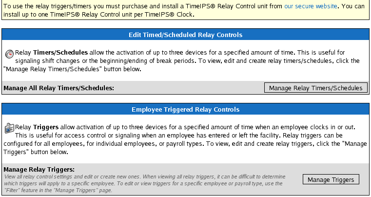
Applies to versions: 1.3, 1.4, 1.5, 1.6, 1.8, 1.9, 1.10, 1.11, 2.0, 2.1, 2.2, 2.3, 2.4, 2.5


Relay Control: Example - Signaling the beginning/end of a shift


This example explains how to install and setup the Relay Control device to signal the beginning and/or end of a work shift.


  1. Plan your needed relay control actions.

    Our example shift is an 8:00 am - 5:00 pm shift with lunch from 12:00 pm - 1:00 pm. There is a morning break from 10:00 am - 10:15 am and an afternoon break from 3:00 pm - 3:15 pm. Our desired behavior is to signal our employees at the beginning and end of the shift, lunch, and both breaks.
  2.  


  3. Choose your signalling device.

    In our example, a warehouse or indoor manufacturing environment, a 3 second signal on an electronic buzzer is ideal to indicate the start and end of the shift. A one second signal on the same device can then indicate the start and end of lunch and break times.
    NOTE: Consider your business's needs and environmental conditions when selecting the best device for you. See the Relay Control Example Devices article for a list of example devices.
  4.  


  5. Setup a Timed/Scheduled Relay Control.

    Using the left pane main menu, click on Administration » Clocking » Relay Controls


    1. Click on the Manage Relay Timers/Schedules button.
    2.  


    3. Select/enter the options as indicated in the screenshot (above).
      NOTE: Required fields are indicated by red bullets.

      NOTE: Review the field level instructions on the screen.
    4.  


    5. Click on the Create Timer button to save the relay timer.
      NOTE: Click on the Cancel button to leave the page without saving.
    6.  


    7. Repeat steps B and C to create additional Timed/Scheduled timers for the end of the shift and for each break.
    8.  

  6.  


  7. Install the signalling device and wiring to the TimeIPS Relay Control unit.


    1. Unscrew the two appropriate screws for the relay.


      • If the device should be off when TimeIPS is restarted or shut down, use the Normally Open, NO, and Common, C, wire screw terminals.
      •  


      • If the device should be on when TimeIPS is restarted or shut down, use the Common, C, and Normally Connected, NC, wire screw terminals.
      •  

    2.  


    3. Insert the device and power wires.
    4.  


    5. Screw the leads securely.
    6.  


In our example, the electronic buzzer should be off when TimeIPS is restarted or shut down. We therefore connect the power supply lead to the normally open, NO, wire screw terminal and the device lead to the common, C, wire screw terminal.

NOTE: If the device's power is disconnected or turned off, the device will revert to its fail safe or fail secure mode as manufactured.


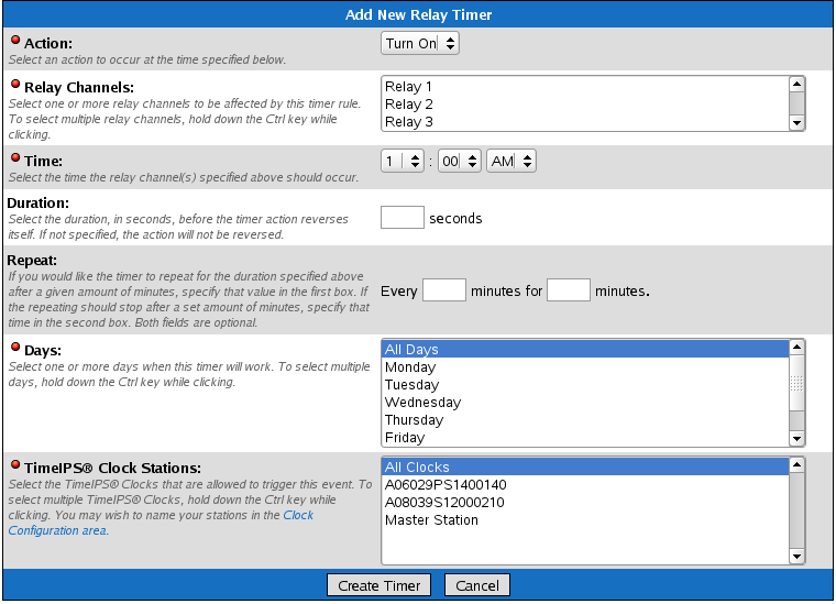
The Timed/Scheduled Relay Control rules we set in step 3 will reverse the buzzers normally open circuit to a connected position for 3 seconds at 8:00 am and 5:00 pm and 1 second for each break.

TIP: You could connect additional devices, utilizing up to 5 amperes, to the same circuits for control by Channel 1. You could also connect additional devices to Channels 2 and 3 and setup additional Relay Control rules for the corresponding relays to control those devices separate from the Channel 1 device.


See Also:
Relay Control Device (1.3, 1.4, 1.5, 1.6, 1.8, 1.9, 1.10, 1.11, 2.0, 2.1, 2.2, 2.3, 2.4, 2.5, 3.0, 3.1, 3.2)
Providing Access Control between 2 areas Example (1.3, 1.4, 1.5, 1.6, 1.8, 1.9, 1.10, 1.11, 2.0, 2.1, 2.2, 2.3, 2.4, 2.5)
Example Devices for use with TimeIPS Relay Control (1.3, 1.4, 1.5, 1.6, 1.8, 1.9, 1.10, 1.11, 2.0, 2.1, 2.2, 2.3, 2.4, 2.5, 3.0, 3.1, 3.2)
Modules/Upgrades (1.3, 1.4, 1.5, 1.6)
Troubleshooting: Relay Does not Sound Buzzer (1.3, 1.4, 1.5, 1.6, 1.8, 1.9, 1.10, 1.11, 2.0, 2.1, 2.2, 2.3, 2.4, 2.5, 3.0, 3.1, 3.2)

Was this article relevant to your question? Yes No
©2004-2023 TimeIPS, Inc. All Rights Reserved - TimeIPS and the TimeIPS logo are registered trademarks of TimeIPS, Inc.
"Intelligent Personnel System" "Run your Business. We'll watch the clock." are trademarks of TimeIPS, Inc.
TimeIPS is protected by one or more patents. Patent No. US 7,114.684 B2.