|
|
Applies to versions: 1.4
Connect Components
The TimeIPS station is the core of the system. Install the additional components using the following steps:
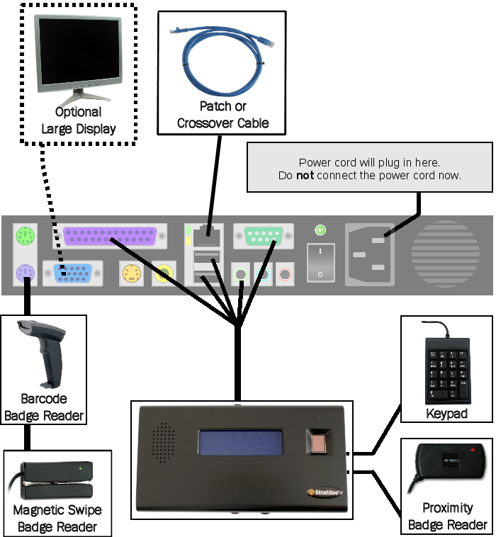
Step 1) Attach the TimeIPS LCD Display and, optionally, a VGA display.
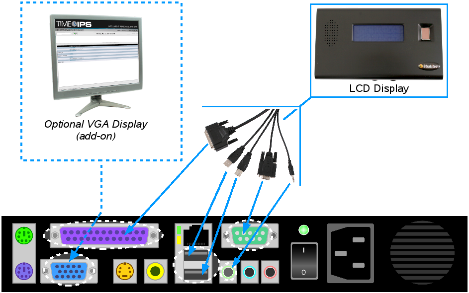
Additional information for large VGA Display (LCD or monitor):
Any optionally connected VGA display, or "large display," operates at a fixed resolution of 1024x768. On LCD large displays (as shown above left) be sure to press the auto button after the TimeIPS station is running for the best display quality. Please note you can also use any standard VGA monitor, depending on your situation and display needs. If more cable length is required, use a high-quality VGA extension cable. See www.timeips.com for options.
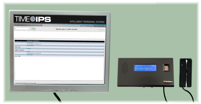
A large display can be used to enlarge the contents of the TimeIPS LCD display or to show who is currently clocked in by department, as shown in the example installation above. Showing who is currently clocked in, the "Current In Employees" view, can be useful in identifying at a glance who is on the premises, to ensure employees have clocked out, and to determine jobs currently in progress.
NOTE: The "Who's Clocked-In" screen for large displays at clock-in/clock-out points is standard with every TimeIPS Intelligent Personnel System. In TimeIPS, navigate to Administration » System Administration » Modules/Upgrades to find out more about upgrading your TimeIPS Time and Attendance System with the IPSIPS Intelligent Personnel System module.
TimeIPS is designed to allow you to plug in a large display at any time. You do not need to turn off the power first when plugging in a Large display (see "Connect Components" Step 1 for instructions on connecting an optional VGA monitor). You do not need to disconnect the small LCD display in order to connect a large display. Both will work at the same time.
|
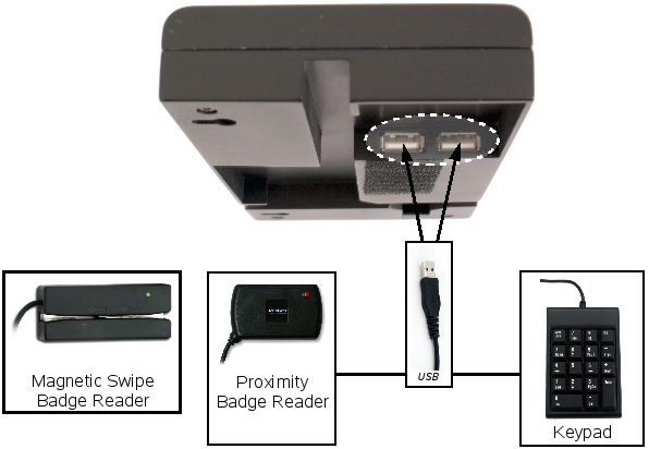
Step 2) Attach USB Employee Identification Device(s) to the back of the LCD Display.
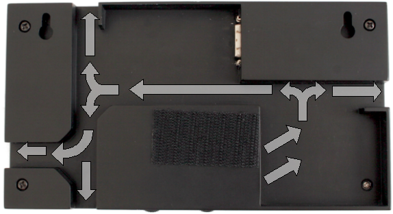
Plug in up to 2 USB Employee Identification Devices to the back of the LCD Display and route the cables through the back channels of the display, or directly into the wall for a more permanent mount.
Additional Information:
Cable opening covers are provided to cover unused cable channels.
If more cable length is required, use a high quality USB extension cable. A USB Powered Hub may be required if extending the length more than 32 feet. See www.timeips.com for options.
|
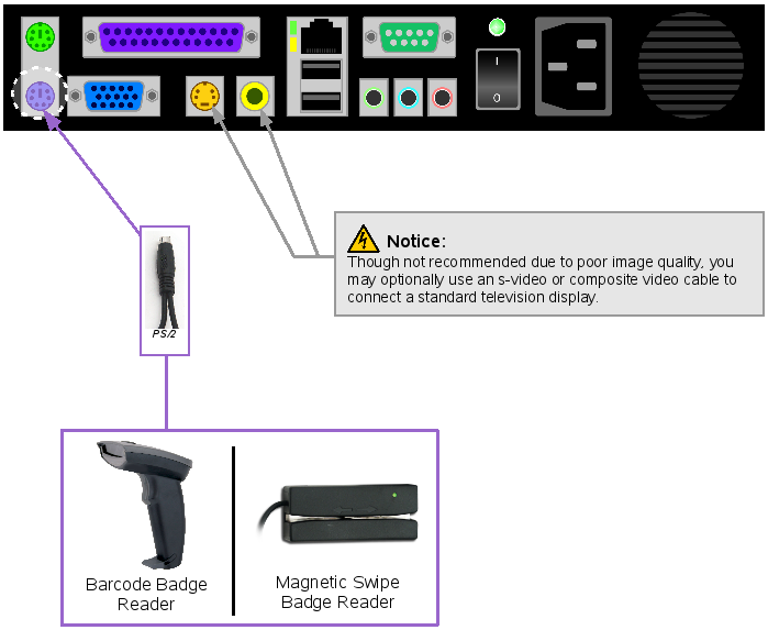
Step 3) Attach any PS/2 Employee Identification Devices to the back of the TimeIPS System.
TimeIPS Barcode readers and magnetic swipe readers may be USB or PS/2. USB devices can be connected to the back of the LCD Display (see Connect Components Step 2). PS/2 devices can be connected to the back of the TimeIPS System.
Additional Information
A barcode badge reader or keypad input device is recommended for use with Job Tracking.
If more cable length is required, use high quality PS/2 keyboard extension cable. See www.timeips.com for options.
|
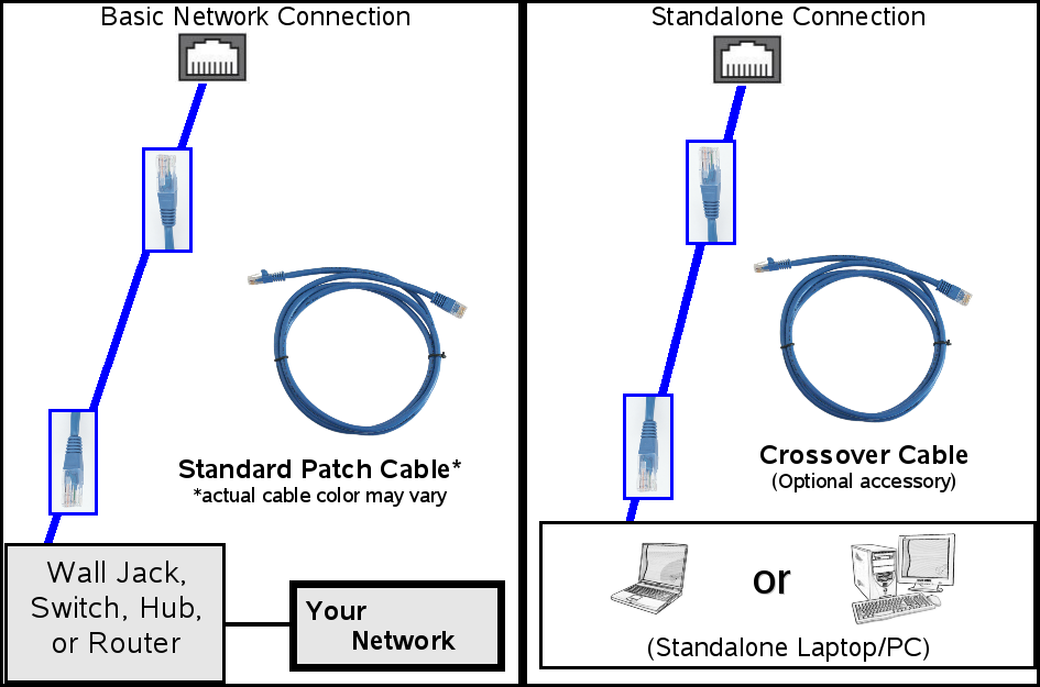
Step 4) Connect the ethernet cable to the back of the TimeIPS System.
TimeIPS can be connected to existing network or directly connected to a standalone PC.
IMPORTANT: A local area network (LAN) is recommended for configuration and operation of TimeIPS as an Internet connection is required to use e-mail alerts, to Automatically update TimeIPS software, and to keep accurate time by continuously synchronizing with an Internet-based time server.
Neither a computer or an Internet connection is required for employee's to clock in and out from the master station. A computer is required to access the Administrative sections to run time reports and payroll.
Existing Network |
No Network (standalone) |
| Connect the included Standard Patch cable in the RJ-45 port in the back of the TimeIPS System. Connect the other end to an ethernet wall jack, switch, hub, or router. |
Connect the optional, labelled Crossover Cable cable in the RJ-45 jack on the back of the TimeIPS System. Connect the other end of cable to the RJ-45 jack on a laptop or PC. |
|
Step 5) Verify connection of components
After verifying the connections, proceed to the TimeIPS Startup to confirm the network connection and set TimeIPS to a static IP address.
See Also:
TimeIPS Startup
Was this article relevant to your question? Yes No |

 Information