316-264-1600 Information Information Sales Sales Support Support |
|
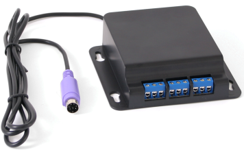
Applies to versions: 1.3, 1.4, 1.5, 1.6, 1.8, 1.9, 1.10, 1.11, 2.0, 2.1, 2.2, 2.3, 2.4, 2.5, 3.0, 3.1, 3.2, 3.3, 4.0Relay ControlNote: The configuration and operation of the RLY-3CH-PS2 and RLY-3CH-USB are identical and are both referred to as a TimeIPS Relay Control System. The RLY-2CH-RJ12 is identical except that only ports 2 and 3 are active (port 1 is not available). The TimeIPS Relay Control System is intended for the following applications:
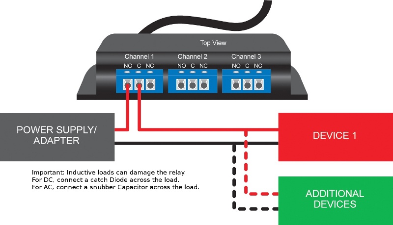
Note: If you have a device that requires more that 5 amps you can use the TimeIPS relay controller to trigger a second relay that is properly rated for your implementation. For an example schematic for wiring something like this click here. See Also: Signaling the beginning/end of a shift Example (1.3, 1.4, 1.5, 1.6, 1.8, 1.9, 1.10, 1.11, 2.0, 2.1, 2.2, 2.3, 2.4, 2.5) Providing Access Control between Two Areas Example (1.3, 1.4, 1.5, 1.6, 1.8, 1.9, 1.10, 1.11, 2.0, 2.1, 2.2, 2.3, 2.4, 2.5) Example Devices for use with TimeIPS Relay Control (1.3, 1.4, 1.5, 1.6, 1.8, 1.9, 1.10, 1.11, 2.0, 2.1, 2.2, 2.3, 2.4, 2.5, 3.0, 3.1, 3.2, 3.3, 4.0) Modules/Upgrades (1.3, 1.4, 1.5, 1.6) Troubleshooting: Relay Does not Activate (1.3, 1.4, 1.5, 1.6, 1.8, 1.9, 1.10, 1.11, 2.0, 2.1, 2.2, 2.3, 2.4, 2.5, 3.0, 3.1, 3.2, 3.3, 4.0) Relay Control Snubber Installation (1.10, 1.11, 2.0, 2.1, 2.2, 2.3, 2.4, 2.5, 3.0, 3.1, 3.2, 3.3, 4.0) 120V Device control with External Relay (2.2, 2.3, 2.4, 2.5, 3.0, 3.1, 3.2, 3.3, 4.0) |

