316-264-1600 Information Information Sales Sales Support Support |
|
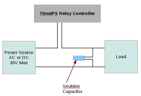
Applies to versions: 1.10, 1.11, 2.0, 2.1, 2.2, 2.3, 2.4, 2.5, 3.0, 3.1, 3.2, 3.3, 4.0Relay Control: Snubber Capacitor InstallationThe TimeIPS Relay Controller can operate intermittently and/or suffer permanent damage from inductive loads unless protected by a snubber capacitor. Examples of inductive loads include magnetic door locks, relays, motors and electromechanical bells/buzzers. To protect the contacts in your relay controller, please connect the snubber capacitor directly across the wires going to the load, as shown below. The snubber capacitor can be used on any load, AC or DC, up to 30V. Although the snubber capacitor can be used for DC loads a catch diode is more effective at protecting the TimeIPS relay controller when using DC. Please use the link at the bottom of this article to see instructions on installing a catch diode.
See Also: Catch Diode Installation Instructions (1.10, 1.11, 2.0, 2.1, 2.2, 2.3, 2.4, 2.5, 3.0, 3.1, 3.2, 3.3, 4.0) |
