316-264-1600 Information Information Sales Sales Support Support |
|
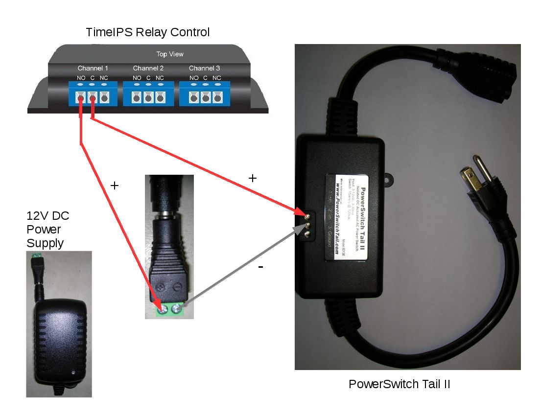
Applies to versions: 2.2, 2.3, 2.4, 2.5, 3.0, 3.1, 3.2, 3.3, 4.0TimeIPS Relay Control - Example connection for 120V DevicesSome applications require the use of a 110V - 120V AC device (such as a large bell/horn, light, etc.) with the TimeIPS relay control. High voltage/power devices should NOT be connected directly to the TimeIPS relay control. The TimeIPS relay control is rated for a maximum of 30V. The exposed connections are not safe for use with higher voltages, such as 120V wiring. We suggest the use of a third party switching device to isolate the 120V AC. A good example of such a device is the "PowerSwitch Tail II" from PowerSwitchTail.com. Please note that TimeIPS has no affiliation with the manufacturer of the PowerSwitch Tail II. We provide this information solely as a suggestion and provide no warranty or support of the third party device. However, TimeIPS has tested the PowerSwitch Tail II with our relay control and found it to be a stable solution. The PowerSwitch Tail II has a built-in 120V plug and 120V outlet and an internal heavy-duty relay control which toggles power to a connected 110V - 120V AC device. This internal relay control requires a separate 3V - 12V DC power source to operate. Using the PowerSwitch Tail II and a separate low voltage power source will protect the TimeIPS relay control from excessive voltage and eliminate the risk involved with handling exposed 120V wiring. This configuration also eliminates the need for a snubber capacitor since there is no excess voltage or switching noise reaching the TimeIPS relay control. A small power source and up to three PowerSwitch Tail II units can be used, one per TimeIPS relay control channel, to operate up to three 120V devices per relay control. As of this writing, the PowerSwitch Tail II is available directly from the manufacturer at the following address. Be sure to purchase the NO (normally open) version. http://www.powerswitchtail.com/ A suitable 12V DC power source is available at the following address as of this writing. The following example wiring diagram depicts how to connect one PowerSwitch Tail II and separate power source to the TimeIPS relay control.
|
